5.8 KiB
ECE 240: Electronic Circuits
Diodes
A diode is a two-terminal device that only allows current to flow in the direction of the arrow.
 (Source:
Wikimedia Commons)
(Source:
Wikimedia Commons)
The current across a diode is, where \(I_s\) is a forced saturation current, \(V\) is the voltage drop across it, and \(V_T\) is the thermal voltage such that \(V_T=\frac{kT}{q}\), where \(T\) is the temperature, \(k\) is the Boltzmann constant, and \(q\) is the charge of an electron:
\[I=I_s\left(e^{V/V_T}-1\right)\]
!!! tip - \(V_T\approx\pu{25 mV}\) at 20°C - \(V_T\approx\pu{20 mV}\) at 25°C
A diode is open when current is flowing reverse the desired direction, resulting in zero current, until the voltage drop becomes so great that it reaches the breakdown voltage \(V_B\). Otherwise, the above current formula is followed.
 (Source:
Wikimedia Commons)
(Source:
Wikimedia Commons)
Diodes are commonly used in rectifier circuits — circuits that convert AC to DC.
By preventing negative voltage, a relatively constant positive DC voltage is obtained. The slight dip between each hill is known as ripple \(\Delta V\).
 (Source:
Wikimedia Commons)
(Source:
Wikimedia Commons)
In a simple series RC circuit, across a diode, Where \(R_LC>>\frac 1 \omega\), and \(f=\frac{\omega}{2\pi}\):
\[\Delta V\approx \frac{I_\text{load}}{2fC}\approx\frac{V_0}{2fR_LC}\]
Zener diodes
A Zener diode is a calibrated diode with a known breakdown voltage, \(V_B\). If the voltage across the diode would be greater than \(V_B\), it is capped at \(V_B\).
 (Source:
Wikimedia Commons)
(Source:
Wikimedia Commons)
Voltage/current biasing
Solving for current for each element in a series returns a negative linear line and other non-linear lines.
- the linear line is the load line, which represents the possible solutions to the circuit when it is loaded
- Depending on the base current \(I_s\), the diode or transistor will be biased toward one of the curves, and the voltage and current will settle on one of the intersections, or bias points.
 (Source:
Wikimedia Commons)
(Source:
Wikimedia Commons)
- To bias current, as \(R\to\infty\) (or, in practical terms, \(R>>diode\)), the slope of the load line \(\to 0\), which results in a constant current.
- To bias voltage, as \(R\to 0\), the slope of the load line \(\to\infty\), which results in a constant voltage.
!!! example
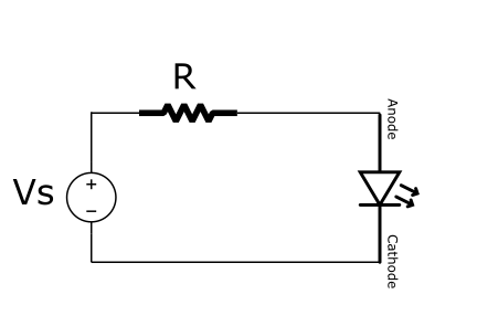
The current across the resistor and the diode is the same:

\begin{align*}
i_D&=\frac{V_s}{R} \\
i_D&\approx I_se^{V_D/V_T}
\end{align*}
If a diode is put in series with AC and DC voltage sources \(V_d(t)\) and \(V_D\):
\[\begin{align*} i_D(t)&=I_se^{(V_D+V_d(t))/V_T} \\ &=\underbrace{I_se^{V_D/V_T}}_\text{bias current}\ \underbrace{e^{V_d(t)/V_T}}_\text{$\approx 1+\frac{V_d}{V_T}$} \\ &=I_D\left(1+\frac{V_d}{V_T}\right) \\ &=\underbrace{I_D}_\text{large signal = bias = DC}+\underbrace{I_D\frac{V_d(t)}{V_T}}_\text{small signal = AC} \end{align*}\]
Diodes may act as resistors, depending on the bias current. They may exhibit a differential resistance: \[r_d=\left(\frac{\partial i_D}{\partial v_D}\right)^{-1} = \frac{V_T}{I_D}\]
!!! example Thus from the previous sequence:
$$i_D(t)=I_D+\frac{1}{r_d}V_d(t)$$Signal analysis
- Analyse DC signals
- assume blocking capacitors are open circuits
- turn off AC sources
- Analyse AC signals
- assume blocking capacitors are shorts
- turn off DC sources
- replace diode with effective resistor (the differential resistor)
!!! tip Most \(R\)s in the circuit can be assumed to be significantly greater than \(r_d\), so \(r_d\) can be removed in series or \(R\) can be removed in parallel.
!!! warning Oftentimes, turning off a DC source to nowhere is actually a short to ground.
MOSFETs
A MOSFET is a transistor. Current flows from the drain to the source, and only if voltage is applied to the gate.
 (Source:
Wikimedia Commons)
(Source:
Wikimedia Commons)
![]() (Source:
Wikimedia Commons)
(Source:
Wikimedia Commons)
In strictly DC, current passes the gate if the gate voltage is greater than the threshold voltage \(V_G>V_t\). The difference between the two is known as the overdrive voltage \(V_{ov}\):
\[V_{ov}=V_G-V_t\]
At a small \(V_{DS}\), or in AC, the slope of \(I_D\) to \(V_{DS}\) is proportional to \(V_G\). The channel transconductance \(g_{DS}\) represents this slope, which is constant based on the transconductance parameter of the device.
\[\frac{I_D}{V_{DS}}=g_{DS}=k_nV_{ov}\]
Before the saturation region, the current grows exponentially:
\[\boxed{I_s=k_n(V_{ov}-\tfrac 1 2V_{DS})V_{DS}}\]
Afterward, it remains constant, based on the overdrive voltage:
\[\boxed{I_s=\frac 1 2k_nV_{ov}^2}\]
Common-source amplifiers
 (Source:
Wikimedia Commons)
(Source:
Wikimedia Commons)
Where \(V_{out}=\)V_{DS}$:
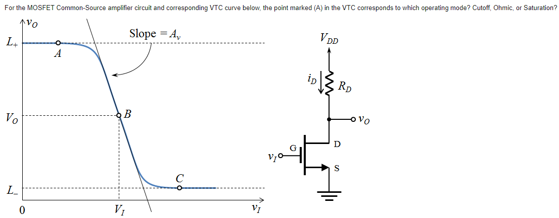
\(|V_{ds}|>|V_{gs}|\) indicates AC voltage gain.
The gain can be modelled with Ohm’s law:
\[V_{DS}=V_{DD}-I_DR_D=V_{DD}-\frac 1 2k_n(V_{GS}-V_t)R_D\]
At a certain gate voltage:
\[\begin{align*} A_V&=\frac{\partial V_{DS}}{\partial V_{GS}} \\ &=-g_{DS}R_D \end{align*}\]